博文

目前显示的是 九月, 2017的博文

5. The design of PCB--design considerations and assembly rules

图片
PCB design considerations   Juvtmall  ( a company supply  PCB Prototyping ,  PCBA service  and sell kinds of  components, modules  and so on)  (1) avoid setting important signal lines on the edge of PCB, such as clock and reset signal. (2) the distance between the ground wire of the enclosure and the signal line is at least 4mm; keep the length and width of the ground wire to be less than 5:1 to reduce the inductance effect. (3) lock the device and line that identified location with LOCK function, so that they will not be misused. (4) the width of the conductor should not be less than 0.2mm (8mil). In high-density and high-precision printed circuit, the width and spacing of the wires are generally preferable to 12mil. (5) Routing in the IC pin of DIP package, 10-10 and 12-12 principles can be applied, as between the two pins by 2 lines, diameter of bonding pad  can be set to 50 mil, width and spacing of line is 10 mil, when only 1 line, diameter can be set to 64 mil, wid

4. The design of PCB-- PCB design related concepts

图片
6. PCB design related concepts                       Juvtmall  ( a company supply  PCB Prototyping ,  PCBA service  and sell kinds of  components, modules  and so on)  Via  holes: Once selected, be sure to deal with  the gap between  it and the surrounding each entity especially easy to ignore  the gap between the line not connected to via hole of  each layer in the middle   and via  hole, if it is a automatic wiring, can be in "number Via minimization" (Via Minimiz8tion) in the sub menu select "on" to automatically solve. The larger load flow required, the larger hole size required, such as the larger the hole in the power layer and the other layer. Silk screen layer: For the convenience of installation and maintenance of the circuit, etc.,  it  need s   printing  logo and  writing code   on the upper and lower surface of the printing  circuit , such as component label and nominal value,   the profile  of   the component  and the signs of the manufa

7.Arduino learning notebook--PWM control the LED

图片
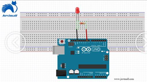
7.Arduino learning notebook--PWM control the LED                       Juvtmall  ( a company supply  PCB Prototyping ,  PCBA service  and sell kinds of  components, modules  and so on)  ( Catduino has the same function of Arduino) This experiment  uses  PWM to control a LED, which slowly turns bright and slowly darkens,  then make a circle .   Here is the wiring diagram: ARDUINO code 1.  / * 2.a uthor: www.geek-workshop.com 3.  components: control board, led, wire, bread board 4.  us age : this experiment demonstrates how to make the  light of  LED  connected to the  port 9 gradually change through the analogWrite() command 5.  * / 6.  int brightness = 0;/ /  define  integer variables brightness and its initial value, this variable is used to represent the LED brightness. 7.i nt fadeAmount = 5;/ / define integer variable fadeAmount, which is used to reduce  or add  the amount of brightness change. 8.  9.  void setup () { 10.  11.  pinMo